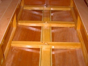
I've finally gotten around to gluing the floors into place once and for all. During the winter I made the pattern for the lead ballast, drilled the bolt holes, and am now waiting for the lead to be poured. With everything pretty much a done deal, I ran out of reasons and just glued them in.
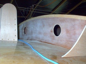
The cabin trim has been added to the front of the house. It was narrow enough and thin enough to just bend into place, drilling and screwing it into place as I went along. The tabernacle is just set into place for now. The fwd extension of the cabin side is just being tried in place as well, we're trying out a number of profiles to find the right one.
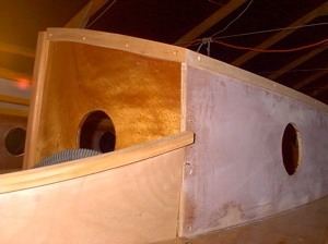
In this view the aft and side trim pieces can be seen. Yes, that rear piece's lower edge is a bit wavy, probably a sanding error. Fortunately, these pieces are not permanently in place yet.
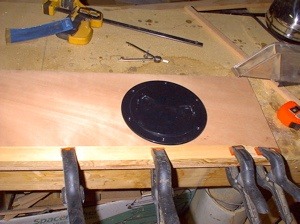
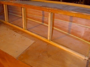
Back inside with the berth fronts; the top beam is added as well as an access hatch to make it easier to get at the bilge board pins once installed.
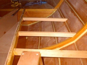
Once the berth fronts are installed the berth top beams are screwed and glued into place. The plans call for a 1 inch square piece along the side of the hull which we will not be including as we are using thicker 9 mm plywood for the berth tops.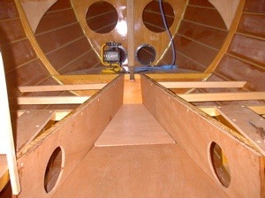
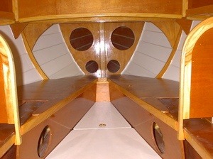
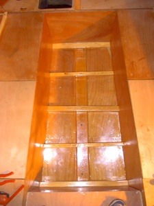
A longer view showing both sides of the cabin with the floor pieces added. The floor is 1/2 inch plywood fitted somewhat loosely for a comfortable fit to make it easy to remove with the brass lifting rings that I'll add later on.
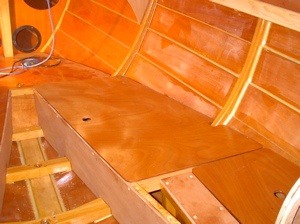
The berth tops in place. The small triangular piece needs to be fitted. The bilge board caps are a little higher than the berth tops but the cushion will make this unimportant.
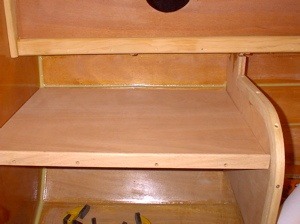
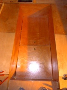
The galley work surface. We decided to simplify the layout to one surface for the stove etc. and have good front access to the storage space below. We found the galley as designed was too low for us to work at. On the opposite side of the cabin we'll have space to store (but probably not use) a port-a-potty or a cooler and other essentials. The electrical panel will be located on the starboard side as well.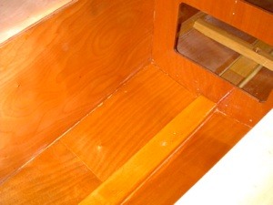
Back outside, the bottom of the cockpit has been given a good sanding and a fresh coat of resin in preparation for the installation of the cockpit floors. I still have two deadwood bolts to install here.
Finally, a view to show how it all goes together. The results are very pleasing. You just never know how well it will work until you peel off the masking tape. The floors are painted with anti-skid paint to match the hull sides colour.
This shot shows the bit of framing that goes behind the seat backs in the cockpit. All the enclosed space with the exception of gluing surfaces will be thoroughly painted before the seat backs go on.
The 1/2 inch plywood floorboards are fitted. They fit loosely allowing water to flow past them into the lower cockpit to be pumped out by a bilge pump at the forward end. The forward panel has since been modified to allow more clearance for the pump. The floorboards will probably be stored in the cabin when not in use.
This aerial view of the cockpit shows the floors finally installed. The motor well is at the top of the picture. The end and middle floors are full depth while the intermediates are shallower and only attach to the cockpit sides.